Arduino Nano & ESP8266 Web Server
Simple light control through web page

During the holidays I decided I wanted to make a light control to allow me leave some lights on while reading at nighttime and turn them off automatically in case I’d fall asleep, hence I decided to go back to my ol’ Arduino and found this compatible version of the Arduino Nano on Amazon at a very low price: 3 for 14$.
Since I wanted others to control the lights, even those with an iPhone I couldn’t just use bluetooth and make an experimental app for the smartphone so I decided to use WiFi instead and instantly looked for an Arduino module: ESP8266


The module works with a tension of 3V3 but the Arduino Nano is not powerful enough to provide the correct current so that required a 3V3 regulator.
As last thing, of course, the lights: I bought some at a Flying Tiger but they can be easily found everywhere (e.g.: Amazon). It can also be a simple white led or maybe a relay for something bigger.
How it works
1 — Init Phase

During this phase the Arduino configures the ESP8266 sending some commands:
- Reset the module
- Connect to AP
- Set WiFi mode to station mode
- Show IP
- Accept multiple connections
- Start server on port 80
Each one of this command has a timeout which may be too little, that’s why I highly advise to be careful during this phase and do a lot of debug with the serial monitor.
2 — Get control
The /control page provides a static html webpage with a simple form to perform an HTTP request to the /light endpoint.
3 — Send command
With the help of jQuery after the OK button is pressed an HTTP request is made to the /light endpoint with two params: power and timeout.
power is the value 0–255 for the analogWrite on the light port and timeout is a value expressed in seconds after which the lights will turn off. If the timeout is 0 no timer will be set.
Wiring
Prerequisite
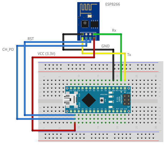
Before starting with the code it is necessary changing the baudrate of the ESP8266 which is 115200 by default. We will set it to 9600, to do so simply upload the BareMinimum code and connect the ESP as follow.
After that, open the serial monitor and after setting line ending with Both NL & CL, and baudrate to 115200 send the command:
AT+UART_DEF=9600,8,1,0,0

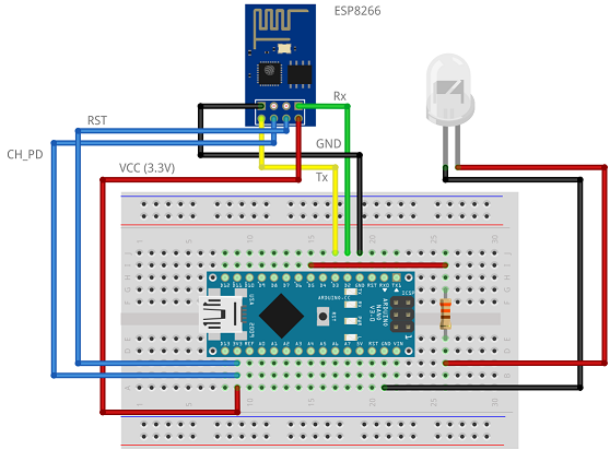
Final wiring
Now we can finally connect the TX/RX ports of the WiFi module to different pins on the Arduino to differenciate the communication between PC<->Arduino and Arduino<->ESP, and also connect the lights.
The code

Focus on…
… different handling for /control & /light
Memory difference
The /control page has to only serve a static content wich is almost 1KB in size, that’s why it was stored inside the Flash Memory (32KB) instead of the SRAM (2 KB), see line #17. Same was done for the HTTP header (line #16), used by /light, which is copied to a buffer (500B) and then modified every time it is needed.
The /light endpoint, instead, has the sole purpose to get some data and store it inside some variables that will be later used to command the lights.
An HTTP call without any data given back is not cool to see, that’s why I added a JSON response.
Sending mode
The real difference between the two pages is that for /control all the data, including the header is sent directly to the WiFi module without storing anything inside the SRAM, that’s how you serve a big static content, while for the /light the header is first copied into a variable, modified (changing CONTENT-LENGTH and CONTENT-TYPE headers) and then the content is appended to it.
Content-length
Another difference between /control and /light is the way in which the client receives the content. With /light the header holds the content-length, that’s how the client understands when all the data was transfered, with /control there’s not explicit length hence the client knows all the data was trasfered when the connection is closed (line #157).
This was done just to prove it would work either way, it’s very easy to add the content length to a static content.
… memory
Yes, handling memory was a real pain in the neck.
Every once in a while the code stopped running and without a proper way of debbugging, if not with prints on the serial monitor, figuring out the problem was really hard. There is a function, availableMemory(), that returns the available memory when called. It tries to allocate memory with a malloc, starting from 2048B downward.
It was using this very simple function that I figured out that I had some memory leaks with dynamics Strings.
F(“String”)
Some may not now but printing on the serial monitor static strings occupy SRAM memory. Using F(“String”) instead of “String” stores the value in the Flash memory and helps save some space.
Of course the memory/time thradeoff comes in, but it’s better to see a log 20ms later than not seeing it at all.
It is possible to see in the code that it was randomly used but it could be used everywhere.
… simple advice
In case you’d try to develop the same thing be careful when using a breadboard. Be sure everything is properly wired and always check for correct power management, in fact the WiFi module was going crazy just because I slightly touched some connections.
What can be done better?
There’s always space for improvement.
- Better logging
- Better errors handling
- Handling OK/KO messages from ESP8266
- Improve code structure and avoid code repetition
- Using libraries (yes, there are libraries that do what I’ve done)
Final touches
To complete the project it was needed to move everything from the breadboard to an actual “pcb”. Well, I couldn’t wait for a pcb to be printed so I decided to use what it’s called “millefori” in Italian. A simple prototype board like this one: https://amzn.to/3bp7pVQ
Using EasyEDA I drawn the printed circuit and then replicated on the board (not successfully though, the components weren’t placed as in the image below).
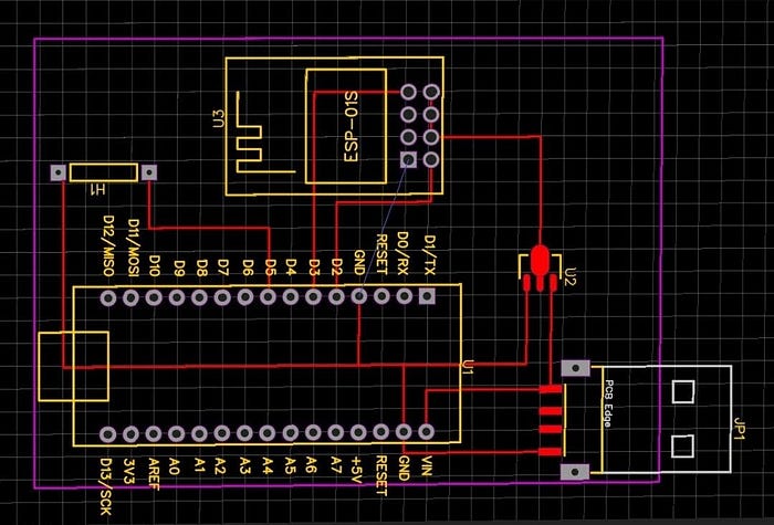
Note that the ground of the ESP module is not connected and a jumper was required. I bet there’s some other way to wire everything wihtout jumpers and using just one layer.


Last thing to be done would be 3D printing a package for it.
Maybe I’ll find the time.
Hope you enjoyed this article! 😃
